Phenomenological calculation strategies for short glass fiber-reinforced, thermoplastic injection molded parts

Due to their outstanding mechanical properties and their extremely low weight, short glass fiber-reinforced thermoplastic injection-molded parts are increasingly being used in applications in which materials, such as steel and aluminum, were previously preferred.
Typical applications include the automotive and aerospace industries. Particularly in the automotive sector, where large quantities are required in a very short time, injection molding is an efficient manufacturing process for plastics, which also allows for a great deal of creative freedom. However, predicting fiber orientation resulting from the process, material, and geometry is a major challenge that is still of great interest in ongoing research.
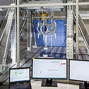
Integrative simulation is one method of incorporating fiber orientation in the design of appropriate molded components. It enables the transfer of relevant process information into coupled structural mechanic simulation with the aid of a suitable interface, thus making it possible to predict the behavior of the respective component. However, the individual steps of the integrative simulation must always be validated and calibrated using experimental data. This means that the process parameters and tool geometries must be known and actual moldings available. Consequently, this concept may be adequately pursued only from a point in part development where prototypes can already be produced.
Aginst this background Fraunhofer LBF developed a new process as part of an IGF project, which enables consideration of the fiber orientation of short glass fiber-reinforced injection-molded parts even if there are no real components or prototypes available.
Development of an injection molding tool for fiber orientation analyses
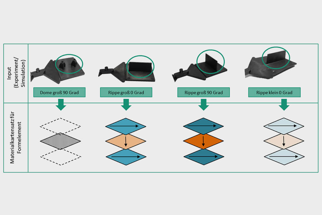
Unlike fully integrative approaches, the assignment of fiber orientation is not based on finite elements but on form elements or significant areas. These can be ribbed, domed, flat areas, etc.
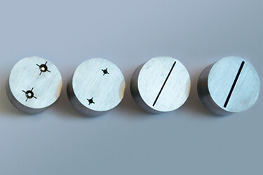
A new molding tool was developed for analysis of fiber orientation based on the geometry of the form element and flow angle. The tool allows for integration of different form elements while maintaining the same molding base. Some of the inserts are shown in the figure besides. Fig. 1: Interchangeable inserts for form elements - from left to right: Big dome, small dome, small rib, big rib.
The new tool makes it possible to analyze the influence of the flow conditions by varying the flow angle. Cost-friendly addition of more inserts is also possible thanks to this concept. The tool has two cavities with different wall thicknesses, which can be operated independent of each other. The form elements are mounted on a 60 mm x 60 mm plate.
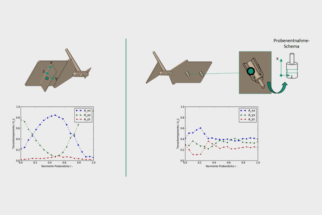
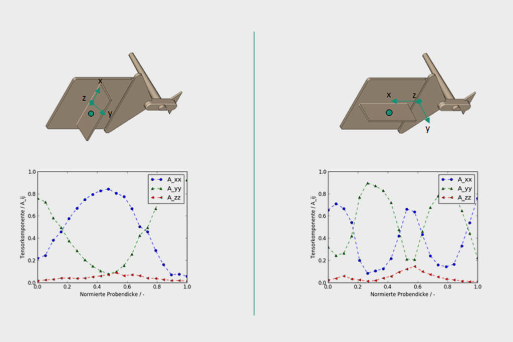
The following are examples of the component variants (see Fig. 2)
Fiber orientation analyses
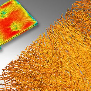
The following results of experimental fiber orientation analyses show just how diverse the fiber orientation is. The graphs below show the major components of the second-order fiber orientation tensor over the normalized sample thickness. The figure below shows examples for results the influence of the form elements..
Below are examples of the analysis of the influence of the flow angle.
Material modeling strategy from orientation distributions
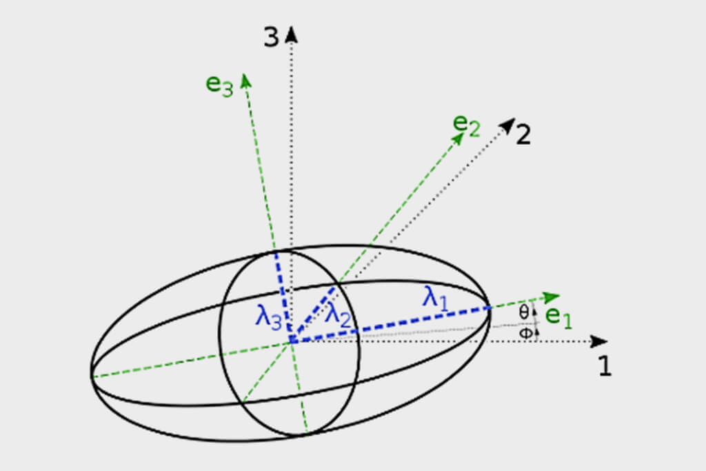
For the modelling of the short fiber reinforced parts through-thickness fiber distribution is considered by applying layered shell setup. The necessary information for the desired modelling method can be derived from the second-order orientation tensor:
- Main orientation (via eigenvector e1)
- Distribution degree (via eigenvalues λ1 )
Definition:
λ1, λ2, λ3, where e1 is the eigenvector associated with the eigenvalue λ1
The information available can then be used to determine the following variables in each layer:
- Degree of anisotropy (DA)
- Preferential orientation
There are different ways of defining the number of layers:
- Change of the orientation distribution (based on the material)
- Manual preset (based on experience)
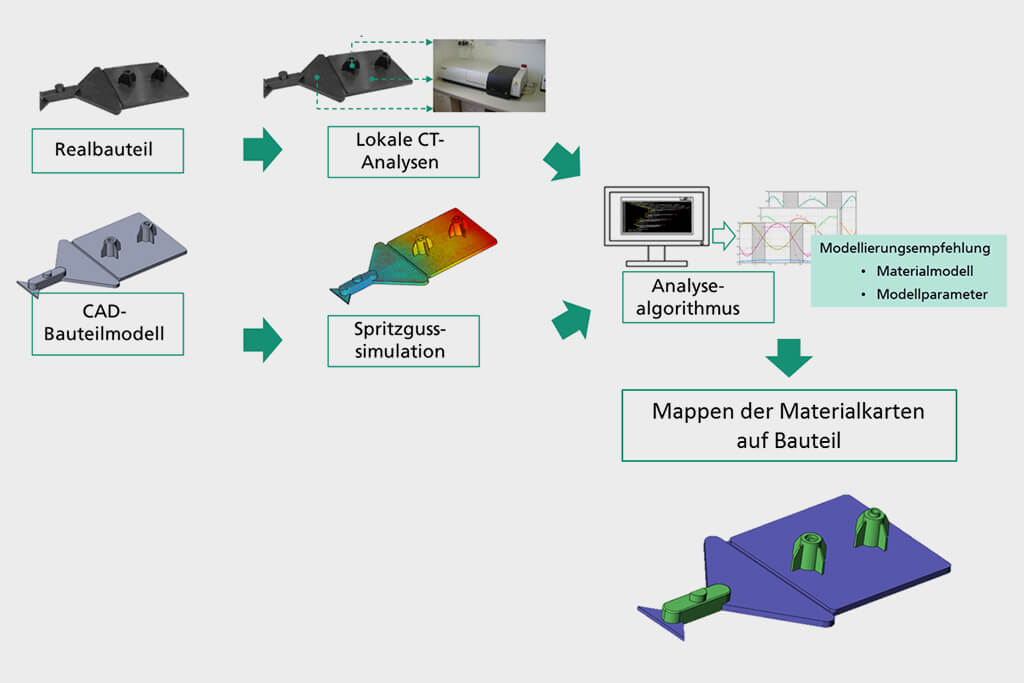
An automatic analysis algorithm is used to determine an appropriate material model for each identified layer, e.g. isotropic or orthotropic, as well as all necessary model parameters. Here, mechanical test data, which can be determined rather easily, is also required in addition to the CT data.
Below is a schematic illustration of the process. The vectors of the individual layers in the material dataset depict the main orientation whereas the colors of the layers offer a schematic representation of the degree of anisotropy/fiber distribution.
Contact
- Markus Fornoff, M.Eng.
- Phone: +49 6151 705-8019
- markus.fornoff@lbf.fraunhofer.de